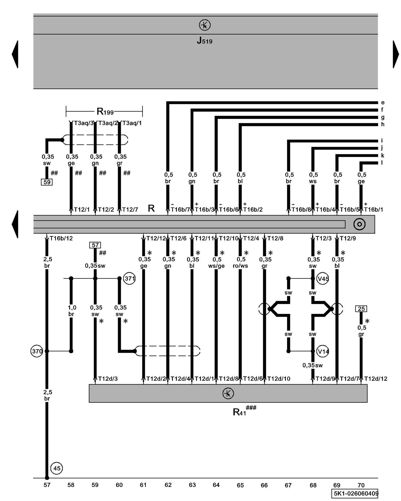
Diagram 26/6 (Tracks 57-70)
IMPORTANT NOTE:
This manufacturer uses "Track" style wiring diagrams.
For information on how to use these diagrams effectively, please refer to Diagram Information and Instructions. Diagram Information and Instructions
Radio, CD Changer, External Audio Source Connector
ws = white
sw = black
ro = red
br = brown
gn = green
bl = blue
gr = grey
li = lilac
ge = yellow
or = orange
rs = pink
J519 - Vehicle Electrical System Control Module Control modules in front part of vehicle - Overview of Control Modules
R - Radio
Locations
R41 - CD Changer
Locations
R199 - External Audio Source Connector
Locations
T3aq - 3-Pin Connector, in glove compartment
T12 - 12-Pin Connector
T12d - 12-Pin Connector
T16b - 16-Pin Connector
(45) - Ground Connection (behind instrument panel, center)
(370) - Ground Connection 5 (in main wiring harness)
(371) - Ground Connection 6 (in main wiring harness)
(V14) - Connection (shielding) (in CD-changer wiring harness)
(V45) - Connection 2 (shielding)(in CD changer wiring harness)
* - Only models with CD changer/ CD changer preparation
## - Only external audio connector in glove compartment
### - Components not available on system preparation
Previous Diagram 26/5 (Tracks 43-56)
Next Diagram 26/7 (Tracks 71-84)