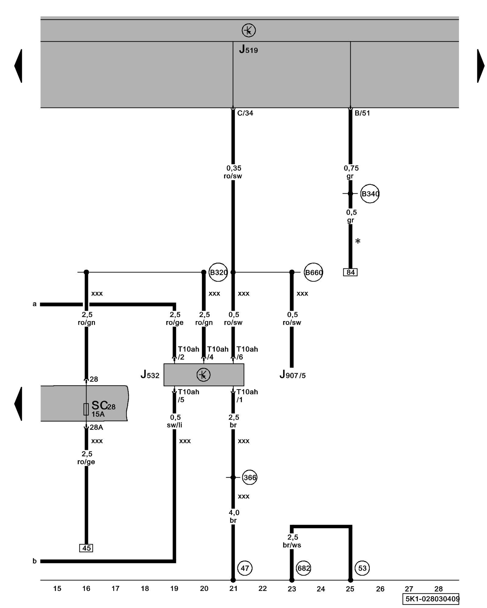
Diagram 28/3 (Tracks 15-28)
IMPORTANT NOTE:
This manufacturer uses "Track" style wiring diagrams.
For information on how to use these diagrams effectively, please refer to Diagram Information and Instructions. Diagram Information and Instructions
Voltage Stabilizer
ws = white
sw = black
ro = red
br = brown
gn = green
bl = blue
gr = grey
li = lilac
ge = yellow
or = orange
rs = pink
J519 - Vehicle Electrical System Control Module Control modules in front part of vehicle - Overview of Control Modules
J532 - Voltage Stabilizer
J907 - Starter Relay 2 Overview Of Relay Carrier
SC28 - Fuse 28 (on fuse panel C) Fuse overview (SA), (SB), (SC)
T10ah - 10-Pin Connector
(47) - Ground Connection (in front right footwell) Overview Of Ground Connections in Interior
(53) - Ground Connection (in rear lid, right) Overview Of Ground Connections in Luggage Compartment
(366) - Ground Connection 1 (in main wiring harness)
(682) - Ground Connection 2 (in right rear side panel) Overview Of Ground Connections in Luggage Compartment
(B320) - Plus Connection 6 (30a) (in main wiring harness)
(B340) - Connection 1 (58d) (in main wiring harness)
(B660) - Connection (diagnostic, terminal 50) in main wiring harness
* - Only models with CD changer/ CD changer preparation
xxx - Only models with stop/start system
Previous Diagram 28/2 (Tracks 1-14)
Next Diagram 28/4 (Tracks 29-42)