Diagram 28/6 (Tracks 57-70)
IMPORTANT NOTE:
This manufacturer uses "Track" style wiring diagrams.
For information on how to use these diagrams effectively, please refer to Diagram Information and Instructions. Diagram Information and Instructions
Radio/Navigation Display Control Module, Operating Electronics and Telephone Control Module
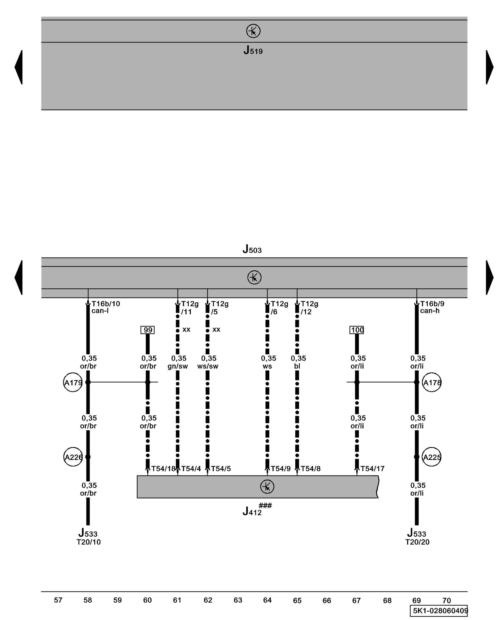
ws = white
sw = black
ro = red
br = brown
gn = green
bl = blue
gr = grey
li = lilac
ge = yellow
or = orange
rs = pink
J412 - Operating Electronics and Telephone Control Module Control Modules in The Rear Of The Vehicle
J503 - Radio/Navigation Display Control Module Locations
J519 - Vehicle Electrical System Control Module Control modules in front part of vehicle - Overview of Control Modules
J533 - Data Bus On Board Diagnostic Interface Control modules in front part of vehicle - Overview of Control Modules
T12g - 12-Pin Connector
T16b - 16-Pin Connector
T20 - 20-Pin Connector
T54 - 54-Pin Connector
(A178) - Infotainment High-Bus Connection (in instrument panel wiring harness)
(A179) - Infotainment Low-bus Connection (in instrument panel wiring harness)
(A225) - Infotainment High-Bus Connection 2 (in instrument panel wiring harness)
(A226) - Infotainment Low-bus Connection 2 (in instrument panel wiring harness)
### - Components not available on system preparation
-^- - Only models with telephone/ telephone preparation
xx - Only Universal Cellular Telephone Preparation (UHV) Low
Previous Diagram 28/5 (Tracks 43-56)
Next Diagram 28/7 (Tracks 71-84)