Temperature Regulator Door Motor (V68)
Temperature Regulator Door Motor (V68)
Removing
- Remove the knee airbag bracket.
- Remove the trim in the left footwell of the center console (it is not necessary to remove the trim any further).
- Remove the driver footwell vent. Refer to => [ Driver Side Footwell Vent ] Driver Side Footwell Vent.
- Remove the data bus on board diagnostic interface (J533).
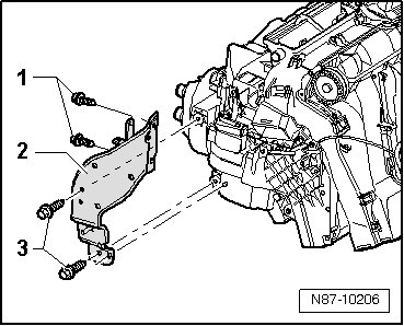
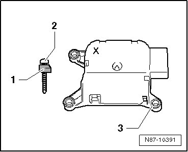
- Remove the bolts - 3 - (9 +/- 1.3 Nm).
• The bolts - 1 - are not to be removed.
• Do not remove the bracket - 2 -.
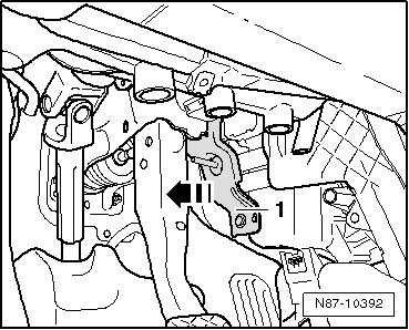
- Push the mount - 1 - in the direction of the brake pedal - arrow - and secure it there with binding components (such as with cable ties).
- Mark the connector - C - for the motor (danger of confusing it with other connectors that may look the same).
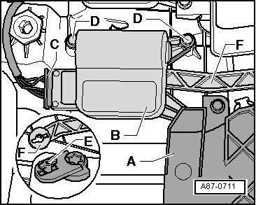
- Disconnect the connector - C - from the temperature regulator door motor.
- Remove the cover - A -.
- Remove the securing bolts - D - (1.4 Nm) and remove the temperature regulator door motor - B -.
- Disconnect the lever - E - from the connecting rod - F -.
Installing
• Optimized motors are marked with an "X".
Use a screw (N 103 254 01) that has been shortened approx. 2 mm to make it easier to install.
- Remove the mount - 1 - from the old temperature regulator door motor with a diagonal cutter.
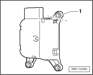
- Attach the new temperature regulator door motor that is marked with an "X" to the mount - 3 - using the shortened raised head screw - 2 - and the removed mount - 1 -.
- After installing, function of temperature door must be checked. Initiate the "basic setting" using the vehicle diagnostic tester.