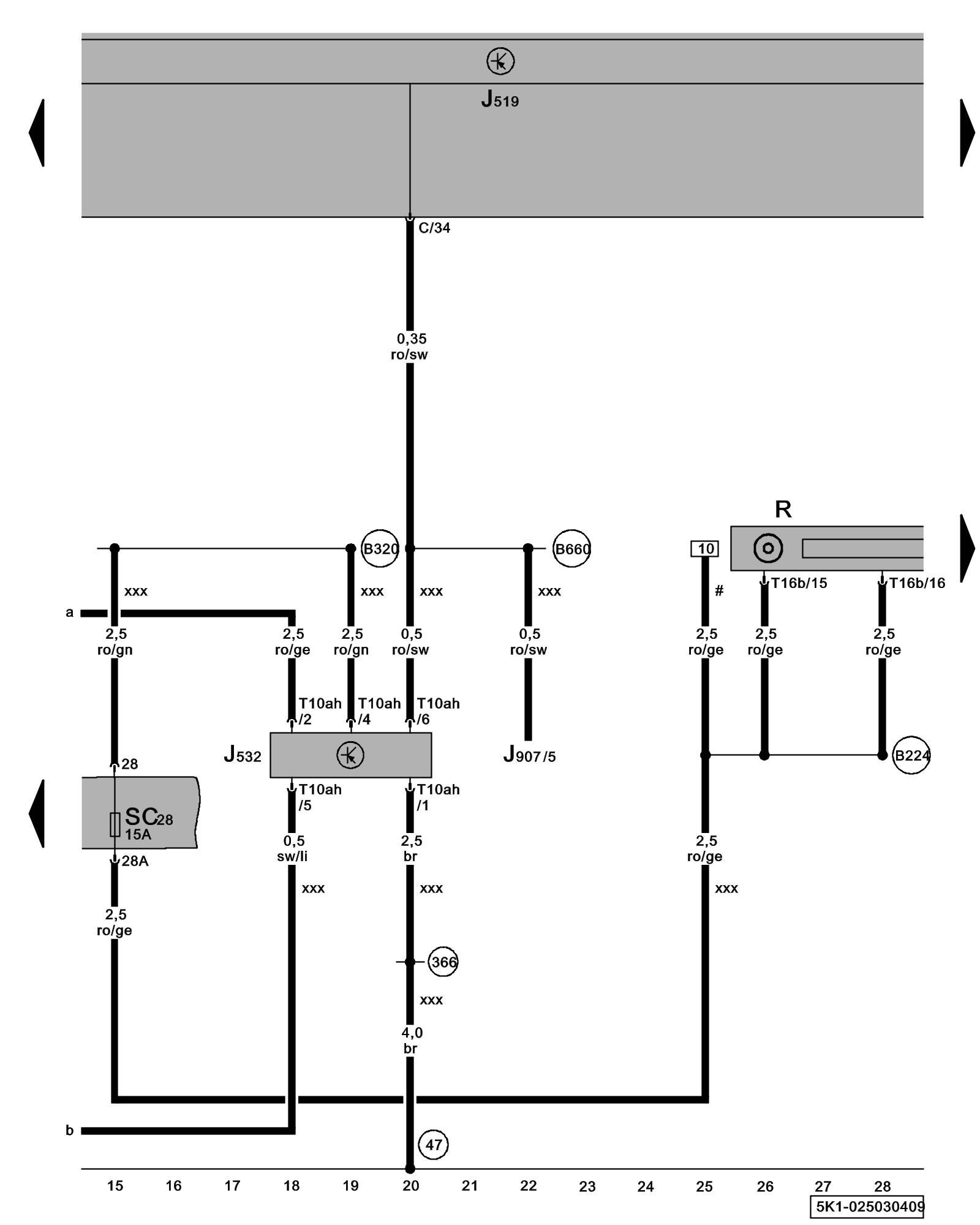
Diagram 25/3 (Tracks 15-28)
IMPORTANT NOTE:
This manufacturer uses "Track" style wiring diagrams.
For information on how to use these diagrams effectively, please refer to Diagram Information and Instructions. Diagram Information and Instructions
Radio, Voltage Stabilizer
ws = white
sw = black
ro = red
br = brown
gn = green
bl = blue
gr = grey
li = lilac
ge = yellow
or = orange
rs = pink
J519 - Vehicle Electrical System Control Module Control modules in front part of vehicle - Overview of Control Modules
J532 - Voltage Stabilizer
J907 - Starter Relay 2 Overview Of Relay Carrier
R - Radio
Locations
SC28 - Fuse 28 (on fuse panel C) Fuse overview (SA), (SB), (SC)
T10ah - 10-Pin Connector
T16b - 16-Pin Connector
(47) - Ground Connection (in front right footwell) Overview Of Ground Connections in Interior
(366) - Ground Connection 1 (in main wiring harness)
(B224) - Radio Connection 1 (in interior wiring harness)
(B320) - Plus Connection 6 (30a) (in main wiring harness)
(B660) - Connection (diagnostic, terminal 50) in main wiring harness
# - Only models without stop/start system
xxx - Only models with stop/start system
Previous Diagram 25/2 (Tracks 1-14)
Next Diagram 25/4 (Tracks 29-42)