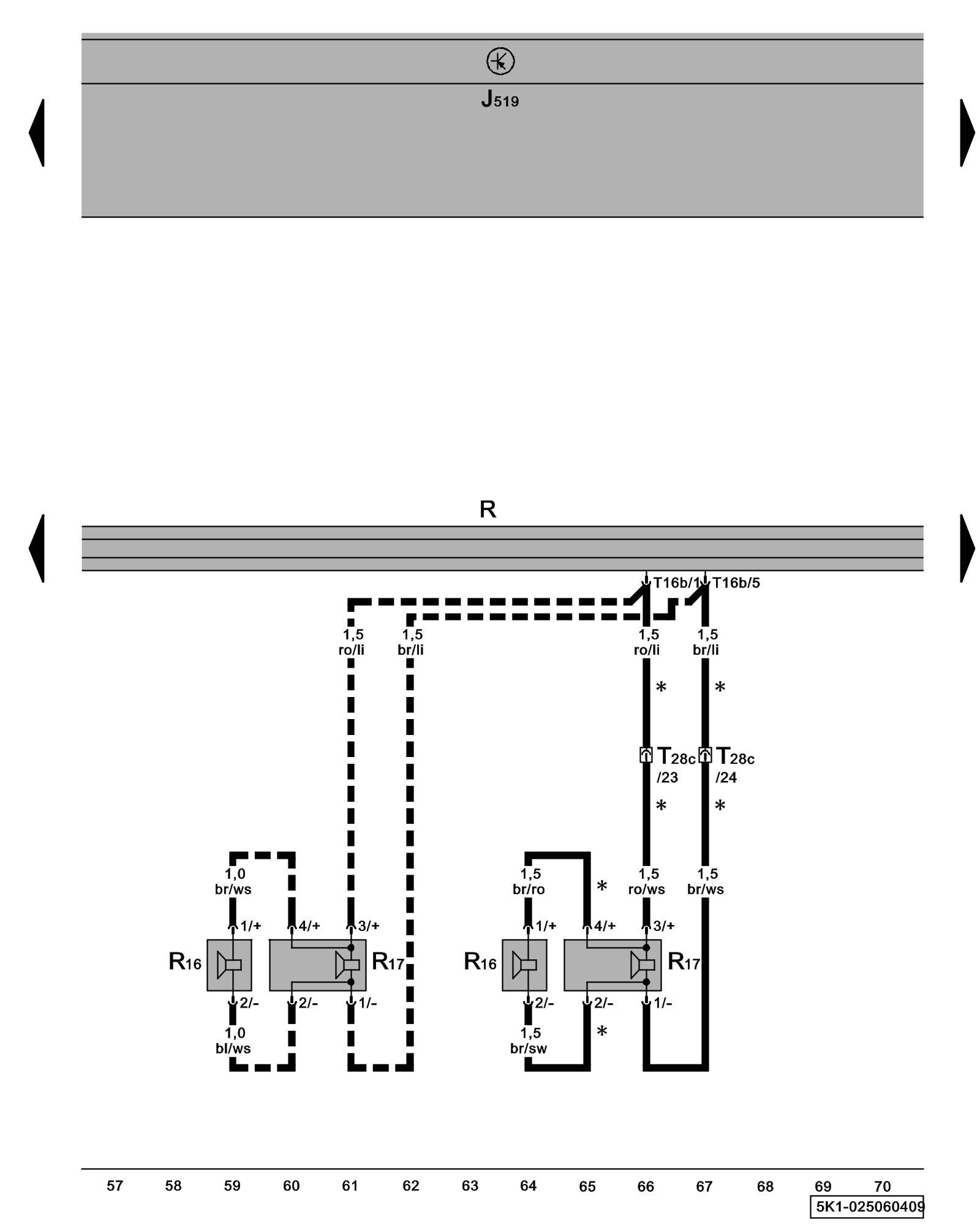
Diagram 25/6 (Tracks 57-70)
IMPORTANT NOTE:
This manufacturer uses "Track" style wiring diagrams.
For information on how to use these diagrams effectively, please refer to Diagram Information and Instructions. Diagram Information and Instructions
Radio, Right Rear Speaker
ws = white
sw = black
ro = red
br = brown
gn = green
bl = blue
gr = grey
li = lilac
ge = yellow
or = orange
rs = pink
J519 - Vehicle Electrical System Control Module Control modules in front part of vehicle - Overview of Control Modules
R - Radio
Locations
R16 - Right Rear Treble Speaker
Locations
R17 - Right Rear Bass Speaker
Locations
T16b - 16-Pin Connector
T28c - 28-Pin Connector, connector station B-pillar, right Overview of connector stations and connectors
* - Only 4-door models with rear speaker
--- - Only 2-door models with rear speaker
Previous Diagram 25/5 (Tracks 43-56)
Next Diagram 25/7 (Tracks 71-84)