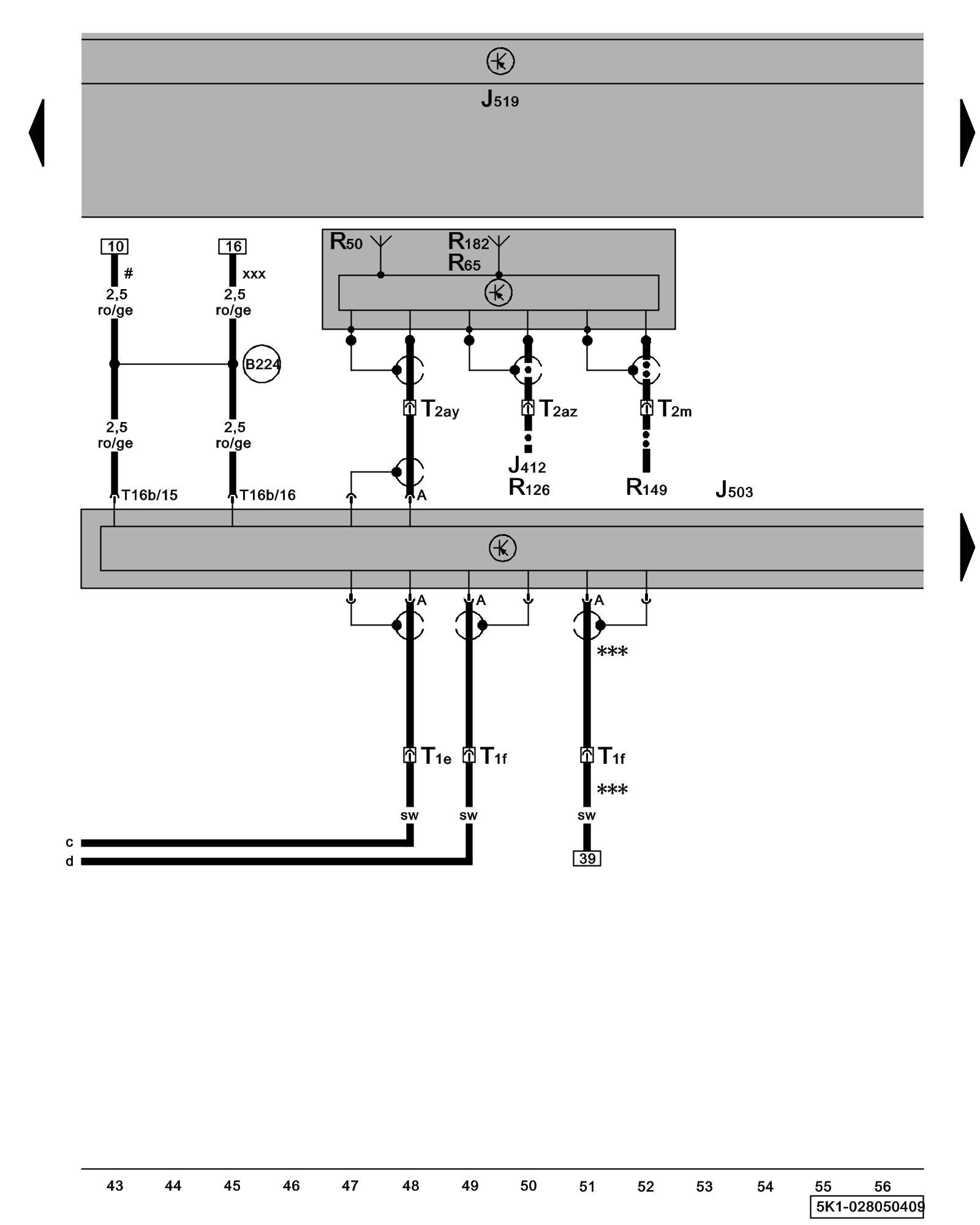
Diagram 28/5 (Tracks 43-56)
IMPORTANT NOTE:
This manufacturer uses "Track" style wiring diagrams.
For information on how to use these diagrams effectively, please refer to Diagram Information and Instructions. Diagram Information and Instructions
Radio/Navigation Display Control Module, Antennas
ws = white
sw = black
ro = red
br = brown
gn = green
bl = blue
gr = grey
li = lilac
ge = yellow
or = orange
rs = pink
J412 - Operating Electronics and Telephone Control Module Control Modules in The Rear Of The Vehicle
J503 - Radio/Navigation Display Control Module
Locations
J519 - Vehicle Electrical System Control Module Control modules in front part of vehicle - Overview of Control Modules
J533 - Data Bus On Board Diagnostic Interface Control modules in front part of vehicle - Overview of Control Modules
R50 - Navigation System Antenna
R65 - Telephone Antenna
R126 - Telephone Baseplate
R149 - Auxiliary Engine Coolant Heating RF Receiver Control Modules in The Rear Of The Vehicle
R182 - Auxiliary Heater Antenna
T1e - Single Connector, behind right C-pillar trim Overview of connector stations and connectors
T1f - Single Connector, behind right C-pillar trim Overview of connector stations and connectors
T2ay - Double Connector, near roof antenna Overview of connector stations and connectors
T2az - Double Connector, near roof antenna Overview of connector stations and connectors
T2m - Double Connector, near roof antenna Overview of connector stations and connectors
T16b - 16-Pin Connector
(B224) - Radio Connection 1 (in interior wiring harness)
-^- - Only models with telephone/ telephone preparation
-^^- - Only models with auxiliary engine coolant heating RF receiver
*** - Only Digital Radio Antenna
# - Only models without stop/start system
xxx - Only models with stop/start system
Previous Diagram 28/4 (Tracks 29-42)
Next Diagram 28/6 (Tracks 57-70)